
Formwork shapes and sizes determine whether a concrete element matches its drawing, fits its reinforcement, and performs its structural role. This guide explains how to get formwork dimensions right, covering standard shapes, size tolerances, and the checks that keep work accurate.
Introduction: Why Formwork Shapes and Sizes Matter
Formwork gives concrete its final geometry. Moreover, once concrete sets, correcting a wrong shape or size becomes expensive and sometimes impossible. Consequently, accuracy at the formwork stage protects both cost and programme.
In addition, wrong dimensions cause knock-on problems. For instance, an undersized column reduces cover to the reinforcement. Similarly, an oversized beam clashes with walls or services. Therefore, technicians must treat every dimension as critical.
This guide therefore covers the standard shapes, the sizes that matter most, and the preparation details that keep formwork accurate.
The Relationship Between Drawing and Formwork
Formwork dimensions come directly from the working drawing. Therefore, technicians must read the drawing correctly before cutting or assembling anything.
Internal vs External Dimensions
The most common error involves internal and external sizes. The drawing usually gives internal concrete dimensions. However, formwork panels are measured and assembled to produce those internal sizes.
Consequently, the technician must account for:
- Panel thickness – the formwork face occupies space outside the concrete.
- Cavity width – the clear distance between faces, which must equal the concrete size.
- Overall external size – the internal size plus twice the panel thickness.
For example, a 300 mm × 300 mm column requires a clear cavity of 300 mm × 300 mm. If the panels are 18 mm thick, the external size becomes 336 mm × 336 mm.
Height and Length Dimensions
Height and length follow the same principle. Moreover, the technician must allow for:
- The base level or kicker.
- The top level or construction joint.
- Any camber or precamber specified for beams and slabs.
Standard Formwork Shapes
Formwork shapes fall into several standard categories. Each shape demands its own fabrication approach.
1. Square and Rectangular Shapes
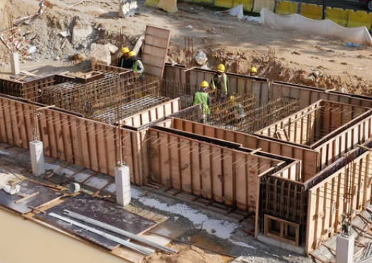
Square and rectangular shapes are the most common. They suit columns, beams, walls, and footings. Furthermore, they are the easiest to fabricate because all angles are right angles.
For these shapes, check diagonals to confirm squareness. If the diagonals are equal, the shape is square.
2. Circular Shapes
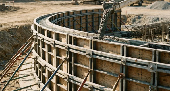
Circular shapes suit columns, piles, and tanks. Workers fabricate them from curved panels, flexible plywood, or steel shells. Moreover, circular formwork must resist hoop stresses, so ties and bands need careful spacing.
3. Polygonal Shapes
Polygonal shapes suit architectural columns and feature elements. They consist of flat panels joined at angles. Consequently, each joint needs a stiffener to hold the angle during casting.
4. Tapered and Conical Shapes
Tapered shapes suit chimney bases, bridge piers, and architectural features. Furthermore, they require adjustable panels or specially fabricated units, because the section changes with height.
5. Curved and Arch Shapes
Curved and arch shapes suit arches, domes, and shell structures. Workers build them from segmental panels or flexible sheeting. Moreover, the centring must support the curve until the concrete gains strength.
6. Complex and Free-Form Shapes
Complex shapes suit architectural concrete with non-standard geometry. They often use fibreglass, plastic, or CNC-cut timber. Consequently, they demand close coordination between designer and fabricator.
Standard Formwork Sizes
Formwork sizes follow standard modules in many countries. Therefore, understanding standard sizes speeds up assembly and reduces cutting waste.
Panel Sizes
Common plywood panel sizes include:
- 2440 mm × 1220 mm (8 ft × 4 ft)
- 2400 mm × 1200 mm
- 1800 mm × 900 mm
Steel formwork panels often follow similar modules, with widths of 300 mm, 450 mm, 600 mm, and 900 mm.
Timber Sizes
Timber members for formwork framing follow standard sections:
- Battens and studs – 50 mm × 75 mm, 50 mm × 100 mm
- Walings and soldiers – 50 mm × 100 mm, 75 mm × 150 mm
- Props – proprietary adjustable props with standard extensions
- Bearers and joists – 50 mm × 100 mm, 75 mm × 100 mm
Element Sizes from the Assessment
The TVET CDACC practical assessment specifies particular sizes. Therefore, technicians should practise these dimensions:
- Column formwork – 300 mm × 300 mm × 2000 mm
- Trench – 1000 mm × 600 mm × depth as drawn
- Scaffold framework – 1050 mm, 750 mm, and 1000 mm dimensions
- Brace spacing on column – 500 mm intervals
These sizes appear repeatedly in assessment checklists. Consequently, accuracy on these dimensions directly earns marks.
Size Tolerances in Formwork
Perfect accuracy is impossible, so standards define acceptable tolerances. Moreover, tolerances tell the technician when to correct and when to accept.
Typical tolerances include:
- Dimensions – ±3 mm to ±6 mm for most elements.
- Plumbness – not more than 1 in 500, or as specified.
- Level – ±5 mm over a 3 m length.
- Squareness – diagonal difference not exceeding 6 mm.
- Straightness – ±3 mm over a 3 m length.
Always check the project specification, because tolerances vary with the element and the standard applied.
Getting the Details Right: Step-by-Step
Accurate formwork results from a sequence of checks. Therefore, follow these steps for every element.
Step 1: Extract Dimensions from the Drawing
First, read all dimensions from the working drawing. Note internal sizes, heights, and levels. Moreover, record any special notes on cover or finish.
Step 2: Convert Internal Sizes to Formwork Sizes
Next, add panel thickness to internal sizes to obtain external sizes. Furthermore, subtract for any rebates or chamfers.
Step 3: Cut Panels and Members Accurately
Then, measure and mark each panel before cutting. Use a try square to mark right angles. Moreover, cut on the waste side of the line so the finished size stays correct.
Step 4: Dry-Assemble and Check
Before fixing, dry-assemble the panels. Check internal dimensions with a tape measure. In addition, check diagonals for squareness.
Step 5: Check Plumbness and Level
During erection, check plumbness with a plumb bob or spirit level. Moreover, check levels at the base and top. Correct any error before tightening braces.
Step 6: Check Cavity Width and Cover
Confirm the cavity width matches the concrete size. In addition, check that spacers maintain the specified cover to reinforcement.
Step 7: Record and Verify
Finally, record the checked dimensions. Where the specification requires it, obtain verification before casting.
Factors That Affect Formwork Dimensions
Several factors influence the final size of formwork. Therefore, technicians must allow for each one.
- Concrete shrinkage – concrete shrinks as it dries, though formwork sets the wet size.
- Deflection under load – panels and props deflect, so stiffness matters.
- Camber – beams and slabs may need precamber to offset deflection.
- Joint thickness – seals and fillets add to the overall size.
- Release agent thickness – negligible, but it affects finish rather than size.
- Temperature – heat and cold affect timber dimensions slightly.
- Moisture – timber swells when wet, so allow for expansion.
Common Mistakes with Formwork Shapes and Sizes
Many defects trace back to simple dimensional errors. Therefore, avoid the following common mistakes.
- Confusing internal and external dimensions.
- Forgetting to add panel thickness.
- Cutting on the wrong side of the line.
- Neglecting to check diagonals for squareness.
- Ignoring specified tolerances.
- Failing to allow for camber in beams.
- Using warped panels that distort the shape.
- Failing to check cover to reinforcement.
- Making changes on site without approval.
Formwork Shape and Size Checklist
Before casting, confirm the following items.
- □
Internal dimensions match the drawing
- □
External dimensions include panel thickness
- □
Diagonals are equal (squareness)
- □
Heights and levels are correct
- □
Plumbness is within tolerance
- □
Cavity width matches the concrete size
- □
Cover to reinforcement is correct
- □
Camber is applied where specified
- □
Joints are sealed and tight
- □
Openings and inserts are in position
- □
Tolerances are within specification
- □
Inspection is recorded
Conclusion
Formwork shapes and sizes decide whether a concrete element fits its drawing and performs its function. When technicians extract dimensions correctly, convert internal sizes to formwork sizes, and check squareness, plumbness, and level, they produce accurate work.
Moreover, tolerances exist for a reason. Therefore, technicians should check against them and correct errors before casting. As a result, concrete elements meet specification, and costly rework disappears.
Frequently Asked Questions
Why do formwork dimensions differ from concrete dimensions?
Formwork dimensions are usually larger than concrete dimensions, because the drawing gives internal concrete sizes. The technician adds panel thickness to obtain external formwork sizes.
How do I check if formwork is square?
Measure both diagonals of the panel or cavity. If the diagonals are equal, the shape is square. If they differ, adjust the formwork until they match.
What is a typical formwork tolerance?
Typical tolerances are ±3 mm to ±6 mm for dimensions, 1 in 500 for plumbness, and ±5 mm over 3 m for level. Always confirm the project specification.
What sizes are used in the TVET CDACC assessment?
The assessment specifies a 300 mm × 300 mm × 2000 mm column, a trench of 1000 mm × 600 mm, brace spacing of 500 mm, and scaffold dimensions of 1050 mm, 750 mm, and 1000 mm.
Why is camber applied to beam formwork?
Camber offsets the deflection that occurs when the concrete hardens and loads are applied. Therefore, technicians raise the soffit slightly above the specified level.