
Abstract
Timbering works constitute a critical temporary works component in building construction, providing lateral support to excavation faces during foundation and substructure operations. Despite the availability of modern steel and concrete shoring systems, timber remains widely deployed due to its workability, cost-effectiveness, and adaptability to irregular excavation geometries. This guide presents a comprehensive examination of timbering systems, covering materials, components, classification methods, design considerations, and installation procedures. Emphasis is placed on the relationship between soil conditions and timbering selection, with reference to established regulatory frameworks including OSHA tabulated data. The guide concludes by addressing removal procedures and the importance of adequate inspection and maintenance throughout the construction period.
1. Introduction
Timbering, in the context of building construction, refers to the temporary support of excavations using timber members to prevent soil collapse and protect workers and adjacent structures. The practice predates modern engineered shoring systems by centuries, yet remains relevant in contemporary construction, particularly for foundation trenches, service excavations, and shafts where rapid deployment and site-specific adaptability are required.
The fundamental purpose of timbering is threefold: to safeguard personnel working in excavations, to prevent damage to adjacent structures and services, and to permit construction operations to proceed in otherwise unstable ground conditions. While the term is sometimes used interchangeably with “shoring,” a distinction is useful: shoring generally refers to support systems for existing structures, whereas timbering specifically addresses the support of excavation faces.
2. Materials and Components of Timbering Systems
2.1 Timber Selection
The timber used in excavation support must possess adequate strength, durability, and resistance to moisture-induced degradation. Common species include pine, fir, and various locally available hardwoods. In regions such as Nigeria, species such as Abura, Afara, and Obeche are commonly employed for formwork and timbering applications, with selection guided by availability, cost, and structural properties.
Timber members for timbering are typically rough-sawn rather than dressed, as the additional surface finishing offers no structural benefit and increases cost. The moisture content at installation should be considered: green timber will shrink as it dries, potentially loosening the shoring system and requiring re-tightening. Where prolonged exposure to wet conditions is anticipated, preservative treatment with approved products such as creosote or CCA is advisable.
2.2 Principal Components
A timbering system comprises several distinct elements, each performing a specific structural function:
- Sheeting (or Lagging): Horizontal or vertical boards placed directly against the excavation face to retain soil. Sheeting dimensions commonly range from 6 in. × 1 in. to 7 in. × 1½ in., with normal lengths not less than 8 ft. Close sheeting involves placing planks side-by-side with minimal gaps; tight sheeting uses tongue-and-groove or specially edged planks to resist water pressure.
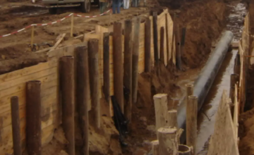
- Poling Boards: Vertical boards driven into the ground ahead of excavation, particularly in loose or running soils. Their chisel-ended lower extremities facilitate driving, while the upper ends are bound with hoop iron to prevent splitting during mauling.
- Walings (Wales): Horizontal members that distribute soil pressure from the sheeting to the struts. Walings are installed with their greater dimension horizontal and must be sized according to the soil type and strut spacing.
- Struts (Cross-braces): Compression members spanning the excavation width, transferring lateral earth pressure between opposing waling systems. Strut sizing and spacing are determined by excavation depth, width, and soil classification.
- Wedges: Tapered timber pieces inserted between struts and walings to enable tightening and adjustment. Folding wedges, used in pairs, permit controlled release during removal operations.

3. Classification of Timbering Systems
3.1 Shallow Trench Timbering
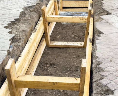
For shallow trenches in firm to moderately firm soils, excavation may proceed to full depth before timbering is installed. The standard arrangement employs vertical sheeting held by walings and struts. In stable cohesive soils, sheeting may be spaced rather than continuous, a technique known as “skip shoring”.
3.2 Deep Trench Timbering
As trench depth increases, earth pressure rises proportionally, necessitating more robust systems. For deep trenches in Type A soil (13 ft depth, 5 ft width), acceptable arrangements include cross-braces ranging from 4×4 at 6 ft horizontal spacing to 6×6 at 12 ft horizontal spacing, with corresponding upright dimensions from 3×8 to 3×8 at varying spacings.
3.3 Running Ground Systems
In running or flowing soils, the sequence of installation differs fundamentally. Excavation proceeds only to the depth the ground will stand without support—sometimes mere inches. Poling boards are then placed vertically against the faces and driven progressively as excavation advances. Walings and struts are installed at progressively lower levels until the required depth is reached. This method demands continuous vigilance, as running ground can exert sudden and substantial loads.
3.4 Shaft and Pit Timbering
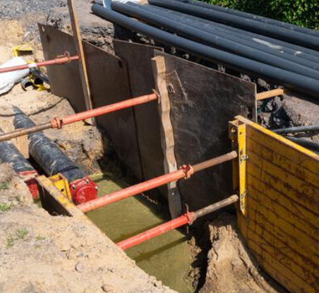
For shafts and pits, timbering systems based on trench methods are adapted to enclosed geometries. In good ground, circular curbs replace walings and struts, with short poling boards fixed behind successive curb rings. In bad ground, a drum curb—a hollow cylinder approximately 3 ft long with internal ribs and a cutting edge—is weighted and sunk as material is excavated from within. For deep circular shafts, cast iron tubbing with flanged and bolted joints may ultimately replace timber, particularly where watertightness is required.
4. Design Considerations and Regulatory Framework
4.1 Soil Classification
Timbering design begins with soil classification. OSHA regulations recognize three soil types: Type A (cohesive, stable), Type B (granular, moderately stable), and Type C (cohesionless, unstable, or subject to water pressure). The soil type determines the minimum member sizes and maximum spacings permitted under tabulated data.
4.2 Use of Tabulated Data
For common trenching situations, pre-engineered tables provide acceptable member sizes and spacings without site-specific engineering analysis. These tables specify cross-brace, upright, and waling dimensions based on soil type, trench depth, and trench width. The tables are limited to situations where: adjacent loads do not exceed a two-foot soil surcharge; cross-brace loads do not exceed 240 lb per linear foot; equipment surcharges do not exceed 20,000 lb; and uniform shoring is used throughout the depth.
Where conditions fall outside these parameters, site-specific design by a qualified engineer is required. Similarly, when timber of different species or condition is used, or when nominal rather than actual dimensions are employed, appropriate adjustments must be made.
4.3 Structural Verification
For critical applications, timber members should be verified against bending, shear, and compression perpendicular to grain. Design values are adjusted by factors including duration of load, moisture content, temperature, and size effects. The National Design Specification for Wood Construction provides the governing reference values and adjustment factors.
5. Installation Procedures
5.1 General Sequence
The installation sequence varies with ground conditions. In firm soils, the typical sequence is: excavate to full depth; place sheeting against faces; install walings; insert and tighten struts. In loose or running soils, the sequence becomes iterative: excavate limited depth; drive poling boards; install walings and struts; repeat.
5.2 Vertical and Horizontal Spacing
Struts should be arranged in vertical planes throughout the excavation length, positioned at distances from the top and bottom not exceeding one-quarter of the depth. Horizontal spacing is governed by the tabulated data or site-specific design, with due consideration for construction access requirements.
5.3 Tightening and Adjustment
Wedges enable progressive tightening as excavation proceeds and as timber dries. In running ground, periodic re-tightening is essential to prevent timbers from becoming loose. Folding wedges, placed in pairs, provide both tightening capability and controlled release during removal.
6. Removal of Timbering
Removal, often termed “striking,” must be conducted with care to avoid sudden soil movement and damage to completed permanent works. The general principle is to backfill progressively as timber is withdrawn, maintaining support to the remaining excavation faces. In the case of foundation trenches, the earth should be returned to both sides of the walling and rammed solid, avoiding displacement of masonry or concrete.
For arch centers, the process of “easing” precedes striking. Easing involves slightly lowering the center to allow the arch to assume its own load before complete removal. This is accomplished by tapping the protruding points of folding wedges, causing the center to drop incrementally.
7. Inspection and Maintenance
Timbering systems are temporary works, but their failure consequences can be catastrophic. Regular inspection is essential, particularly after rain, vibration from adjacent operations, or any indication of soil movement. Inspectors should verify that wedges remain tight, struts are not bowed or displaced, and sheeting shows no signs of distress.
Defective timbers must be replaced promptly. Timber that has sustained impact damage, excessive deflection, or significant decay should not be reused in load-bearing shoring applications.
8. Conclusion
Timbering remains an indispensable technique in building construction, offering a combination of economy, adaptability, and speed that alternative systems cannot always match. Successful timbering depends on accurate soil assessment, correct selection of member sizes and spacings, careful installation, and vigilant maintenance throughout the excavation period. While tabulated data provides a valuable starting point for common conditions, the limitations of such tables must be recognized, and site-specific engineering design employed where conditions deviate from the assumed parameters. When properly executed, timbering works ensure that excavation operations proceed safely and efficiently, protecting both the workforce and the integrity of adjacent structures.